
Thanks to one of my students last year, I became aware of a great free Python script called Maya2Nuke. It lets you set up your scene in Maya and then export it, along with animation information across to Nuke. And it does it extremely well I might add, but not without a little massaging to get there...
I figured a general overview of what this is all about wouldn't hurt here. Some of you may recognise the character above as being the police officer that stops a young James Kirk in the first JJ Abrams Star Trek movie. Note that he didn't originally have a flare in his eye, but more about that later. Its a frame that I sourced from here to use as a personal learning project. No copyright breach intended (it was used for educational purposes)
Whats up, doc?
I'm running Maya 2014. I follow the instructions for the script which says to place it in the user's Maya scripts folder. It then says to import it into Maya from the command line... But it just comes up and can't see anything in Maya. Secondly, it also generates an error trying to retrieve frame numbers. In Maya 2014, these are returned as floats (allowing for fractional frames). The original script tries to treat these as integers, so a small tweak is needed to make the code work.Open up the Python script in a script editor (Maya, Notepad++, etc). Scroll down a few lines (line 29-ish), and there you'll see two lines retrieving start and end frames for the scene into two variables 'min' and 'max'. Its a very simple fix - just typecast these to be integers.

Secondly, once the script is loaded into the script editor, it can just be run from here and performs as you'd expect. However, saving it to the shelf in Maya will just save all that hassle. Its now ready to go.
Front Projection - the what, why and how
Front projection mapping is all about creating the illusion of creating 3D motion from a flat 2D image. It does this by projecting the image as seen through the camera onto the geometry in front of it. Usually you can fake the illusion without front projection through a 2.5D approach using cards or planes with 'slices' of our scenery applied and placed different distances from our camera...But while this may work just fine for distant elements (and it is quite common for cityscapes, etc), for closer details, the fact we are using cards starts to break the illusion as we notice the lack of perspective when moving in or around the scene. Things just look like, well, flat images on cards.
To give our artwork real "depth", we can project the image onto very rough 3D geometry that represents the form of the artwork itself. For example, rock formations with insets and outcrops and buildings that are close by...
Rough you say?
The idea of front projection is to make an image appear to have perspective. This means we're really more concerned with an image appearing to change, and not worried about lighting and rendering artefacts common from rendering low-poly models. For the Star Trek project, I went for a collection of primitive shapes with a little modification here and there.
However, for say a shot of a sky scraper in downtown Los Angeles, simple boxes and a few small extrudes are all that's needed. Here's a very simple example of one that I did earlier as a test.
 |
| K.I.S.S - basic geo just gives our image some depth |
We can get away with fairly low detailed geometry - though high detail may be used in circumstances where intricate details need to have some geometric form.
How do we do it
The approach I use is to simply load up the plate as a background plane in Maya's perspective viewport. Before I proceed, I'll make sure that this fits properly (I've been caught before by not doing this step).- Change the render size to the same dimensions as the picture.
- Make sure we've set the viewport to display the resolution gate (its the small blue ball icon in the VP's status bar). You may need to adjust the Camera attributes - Fit Resolution Gate to a vertical or horizontal option if you can't see the whole image in the viewport.
- Open up the image plane attributes, and make sure that you click the Fit to camera resolution gate option to fit it properly.
- If you don't, you can end up with the image plane not filling the background and the alignment of your scene won't work correctly.

I adjust the camera so that the grid loosely (you don't need to be perfect here - though it can make life a little easier) looks about right and then break up the image into elements that represent the main forms I will see potentially changing with any camera movement.
Model and place the basic forms in the viewport to match the picture. For shapes like faces, or rocky cliffs, you can generate a simple plane or box with multiple faces, and push/pull them to create the basic form as seen from the camera. For the background sky, I'll often generate a very large sphere and cut away the faces to leave a slightly curved background object.
Make sure that you approximate the distances from the camera that the elements sit, align/resize/etc until they look right and you're set. Don't worry if some of the geometry spills outside the camera's resolution gate.

If you want to see your front projection directly in Maya, you just have to wire in the surface colour using a Utility node (rather then a file node). The Utility node is called, oddly enough, Projection. Setting its Proj type to Perspective, adding an image and setting the camera options (Our camera with Resolution Gate being the setting) we can see the result as per the render above.
While you don't need to surface the objects at all for Nuke, there are times where you may want to render directly from Maya rather then go the whole compositing path...
Prepping up the images
Once I have the objects in place and everything looking clean and aligned, I'll break up the original image into multiple layers and paint out details as the elements go backwards... The reason here is simply to make sure if the camera movement starts to reveal what is behind things, we don't want to see that the same picture of the items appear on the background elements...Below is a quick example - I painted into the edges of the house on a layer I was using as a background plate. This meant that the foreground building geometry didn't get any doubled-image issues. Of course, you could also just do a complete sky replace with a separate BG image as well if you wanted to.

Ready to roll...

Run the Maya2Nuke script explained at the start of this article.
Select the items you want to export from the list. If you can't see all items in your scene, look in the Type menu and click the All checkbox.
The Animation menu lets you also process and export animated items.
Under Edit, click the Calculate Maya data - it'll process animated frames, etc.
Then at the very bottom of the window, click the big Generator button.
If it worked out, you'll get a message saying so!
Putting it in NukeX
Just open up Nuke, then click in the Node Graph and paste. The project's nodes should appear, ready to be used. The overall structure is very simple... Our 3D objects (exported by Maya2Nuke as OBJ files) connected into a scene, and then that connected to a scanline render set to use the camera we exported from Maya. A simple example below shows the basic structure of that sky scraper scene. |
| Simple 3D node set up - just add textures and cook. |
You'll spot that the nodes are named to match the items in the Maya scene. Unlike my quick examples, you should ideally make sure to give all of your items proper names that make sense. To be honest, this should be a general practise so you can manage your projects efficiently in any CG application.
Something else to be VERY aware of is that if you use objects without renaming them for a project, OBJ's generated from Maya2Nuke will just overwrite any existing files. I ran into this headache when a fairly complex example I'd created suddenly broke badly. Lucky I just re-exported the Maya scene to overwrite the overwritten files again.
The only thing left to do in Nuke is add a few read nodes to get our images, attach these to Project3D nodes driven by the camera node. And then attach them into the objects. To animate your shot, you will need to get a second camera node - do not animate the one from Maya directly as this one is used to project the imagery onto the 3D geometry itself.
 |
| Oooh! Look - a lens flare! |
To this scene I separated the background and character into two scanline renders. The reason for this was so I could grade and manipulate these two elements separately if I wished. I also threw in an anamorphic flare streak I rendered from LightWave3D to add some animated detail to the eye of the character. Here is a full image of the finished Node graph. I've splattered a good collection of notes through it to hopefully explain what does what...
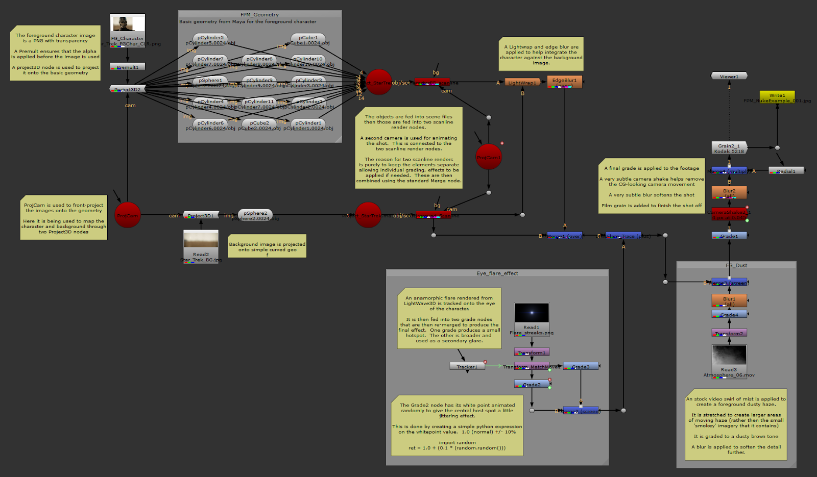 |
| Notes, notes and more notes... |
I didn't really have much of a story behind this scene (it was a mere exercise as a way to test Maya2Nuke, and to prep up for class with an interesting example of front projection), so there's nothing overly exciting going on other then the eye and a slow camera pan (which shows off the perspective effect nicely)

So there you have it - a fairly long-winded explanation and overview of front projection mapping between Maya and Nuke. Its a load of fun, and lets you quickly create moving backdrops and elements from matte paintings, photo's and images.
Its well worth learning to do - front projection is something that's used throughout many a visual effects shot... Hope that this article has been of interest to someone out there on the Interweb...


